
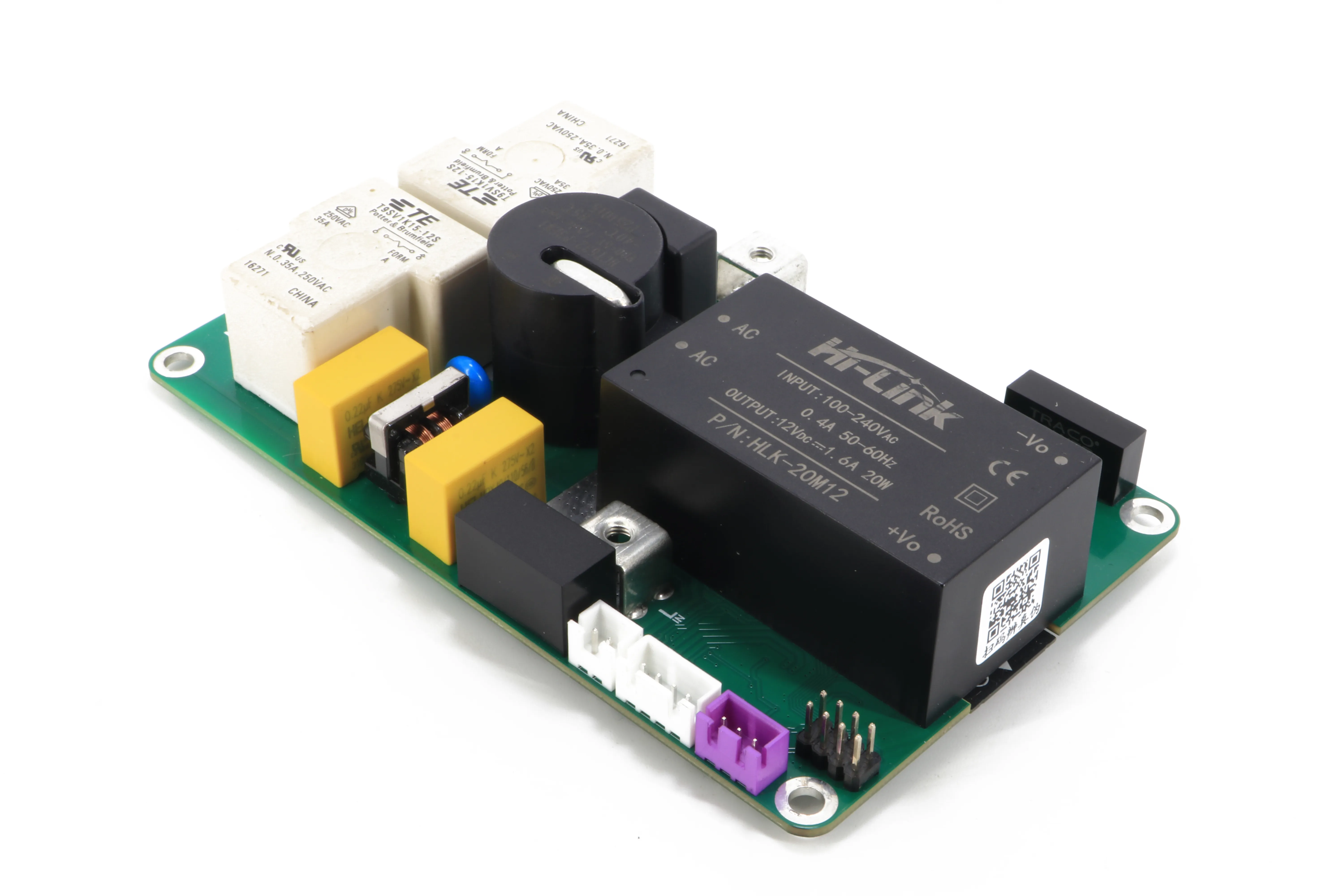
This manual is written for three readers and ordered so each can stop where their job ends: the equipment manufacturer who builds the board into a charger, the electrician who installs it, and the end user who plugs in a car.
1 · Safety information
The board switches mains voltage to a vehicle. Incorrect installation or use can cause electric shock or fire.
Before you start
- Installation, electrical connection and commissioning must be performed by a qualified electrician in line with local regulations.
- The board must be supplied from a dedicated circuit with the upstream protection specified in section 5.
- The board must be connected to protective earth (PE). Never operate it without earth.
- Do not install or operate a unit that is damaged, has a damaged cable, or has been dropped.
- Do not use adapters or extension leads between the charger and the vehicle.
Installation codes
| Region | Code |
|---|---|
| EU | HD 60364 (IEC 60364), with IEC 61851 for EV charging equipment |
| Germany | DIN VDE 0100-722 |
| France | NF C 15-100 |
| United Kingdom | BS 7671, section 722 |
2 · Product overview
BoxBox Lite is an offline AC charging controller. There is no app, no cloud account and no screen: the board talks to the vehicle over the standard control pilot, closes the supply when the vehicle asks for power, and shows what it is doing on a five-light status ring. One button selects the charging current, and the setting survives a power cut.
Key features
- Single-phase 230 V AC, up to 32 A (7.2 kW).
- Plug-and-play — charging starts automatically when the vehicle is ready.
- Five current levels: 6, 10, 16, 24 and 32 A.
- Built-in Type B residual current detection, including 6 mA smooth DC.
- Over-current, over-temperature and over-voltage protection.
- On-board power supply, switching, protection and metering — one 130 × 80 mm board.
- No network, cloud service, app or external controller required.
3 · What’s in the box
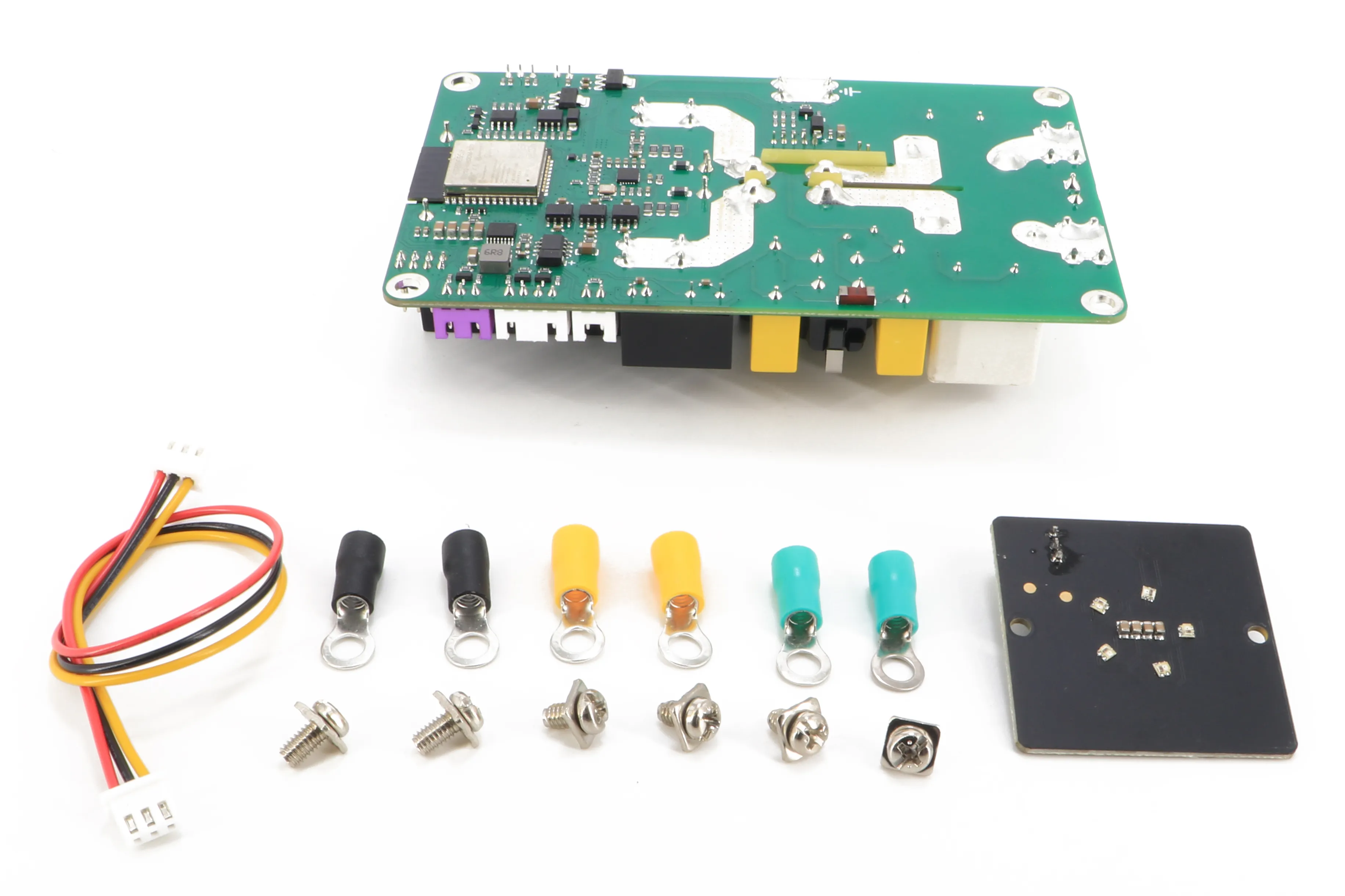
- BoxBox Lite control board
- LED panel, 40 × 40 mm
- Button board, 27 × 27 mm
- 6 × M4 capped terminal screws
- 6 × 5.5-5 copper ring lugs
- LED panel cable and button cable (JST XH, 2.5 mm pitch)
4 · Specifications
| Supply | 230 V AC, single-phase, 50/60 Hz |
|---|---|
| Max current | 32 A |
| Rated power | 7.2 kW |
| Current settings | 6 / 10 / 16 / 24 / 32 A, retained after power loss |
| Control pilot | 1 kHz PWM per IEC 61851-1, states A / B / C / F |
| Residual current | Type B — AC, pulsating DC and smooth DC (6 mA DC per IEC 62955); self-test at boot |
| Over-current | Pause 33.5–35.5 A; latch ≥ 35.5 A |
| Over-temperature | Derate to 16 A at ~90 °C; cut-off at ~105 °C |
| Over-voltage | Cut-out above 270 V; MOV + fuse |
| Standby power | ≈ 3.4 W |
| Metering | Voltage, current, power, energy |
| Controller | ESP32 |
| Interface | Push button, 5 × RGB LED ring |
| Board size | 130 × 80 × 33 mm |
|---|---|
| Weight | 233 g · 259 g with LED panel, screws and lugs |
| Mounting | 4 × Ø 4.2 mm holes for M4 screws |
| Power terminals | M4 screw, for 5.5-5 ring lugs |
| Vehicle connector | Not included — any tethered cable: Type 2, Type 1 / J1772, GB/T |
| Operating temperature | −25 °C to +60 °C |
|---|---|
| Storage temperature | −40 °C to +85 °C |
| Humidity | 5–95 % RH, non-condensing |
| Altitude | up to 2000 m |
| Pollution degree | 2 |
| Overvoltage category | III |
| Earthing systems | TN-S, TN-C-S, TT |
| Ingress protection | None — install in a suitably rated enclosure |
Standards
Control pilot signalling and charging states per IEC 61851-1; residual direct current detection (6 mA DC) per IEC 62955. It is intended for integration into wall-mounted chargers, portable chargers (IC-CPD, IEC 62752) and other AC charging equipment with fixed or tethered cables.
5 · Site & supply requirements
Supply circuit
- A dedicated final circuit — no other loads, sockets or spurs.
- Conductor typically 6 mm² for 32 A continuous; size for the installation method and voltage drop over the run.
- Confirm the incoming supply can carry 32 A continuously alongside existing demand.
Upstream protection
| Device | Typical | Notes |
|---|---|---|
| Over-current (MCB) | 40 A, curve C | Per installation design |
| Residual current (RCD / RCBO) | 30 mA, Type A | Required per local regulations |
Because the board detects 6 mA smooth DC residual current (IEC 62955), a Type A upstream RCD can normally be used instead of a Type B, subject to local regulations.
Earthing
The board must be connected to protective earth. The earthing arrangement (TN or TT, earth electrode, open-PEN protection) must follow local regulations for EV installations. Verify earth continuity and loop impedance.
6 · Board mounting & terminals
The board is supplied without an enclosure. The equipment manufacturer must mount it in an enclosure that provides mechanical protection, the required ingress rating, mains clearance, cable strain relief and user access.
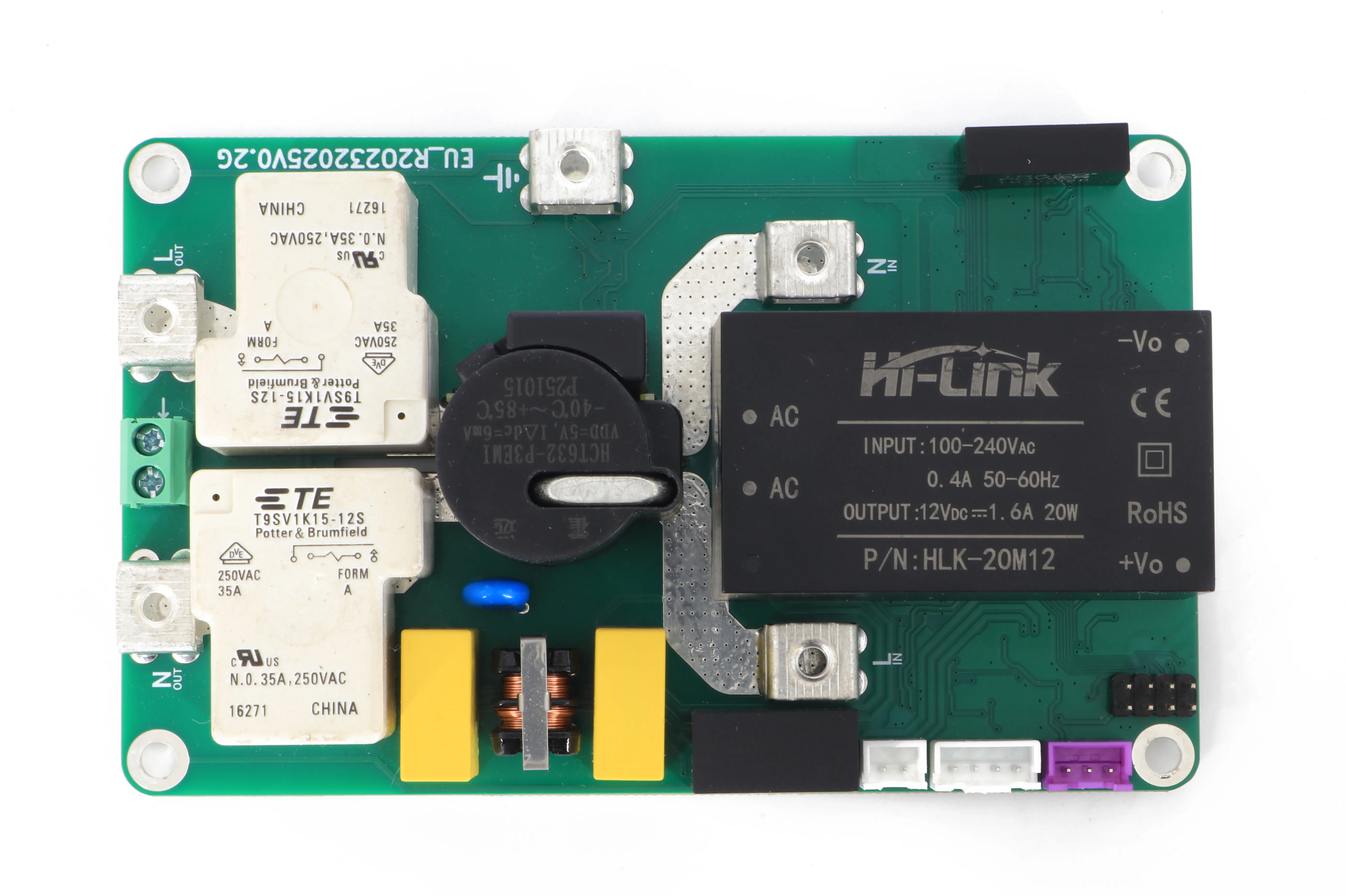 12345678910
- 1L IN — line from supply
- 2N IN — neutral from supply
- 3PE — protective earth
- 4L OUT — line to vehicle
- 5N OUT — neutral to vehicle
- 6CP — control pilot terminal block
- 7Button connector
- 8Screen connector
- 9LED panel connector
- 10Debug header (factory use)
Mounting
- Fix the board with 4 × M4 screws through the Ø 4.2 mm corner holes.
- Use 8 mm insulated standoffs to keep the underside clear of the mounting surface.
- Keep 12 mm clear above the board for components and connector access.
- Do not over-tighten — excessive torque can crack the board or its pads.
Wiring
- Isolate and lock off the supply. Verify dead before touching any terminal.
- Crimp the supplied 5.5-5 ring lugs onto the supply and vehicle-cable conductors.
- Connect L IN, N IN and PE from the supply, and L OUT, N OUT to the vehicle cable.
- Connect the vehicle cable’s control pilot wire to the CP terminal block.
- Connect the LED panel and button cables to their JST connectors.
- Close the enclosure before applying power.
7 · Commissioning
With wiring complete and the enclosure closed, apply power. The board runs a start-up sequence and a residual current self-test automatically.
- Power on — the ring shows spinning colours while the board starts and runs its self-test. The relays stay open.
- Ready — the ring settles to breathing green: self-test passed.
- Test charge — connect a vehicle and confirm moving green and that the vehicle draws current.
- Record — note the firmware version and the selected current level.
8 · Charging a vehicle
BoxBox Lite has no start or stop button — it follows the car.
- Plug in. Charging begins as soon as the car requests power. The ring shows moving green.
- Pause. If the car pauses, the ring stops moving. Charging resumes when the car asks again.
- Unplug to stop. The ring returns to breathing green.
9 · Setting the charging current
The button cycles through five levels: 6 → 10 → 16 → 24 → 32 A. The selected level is kept after a power cut.
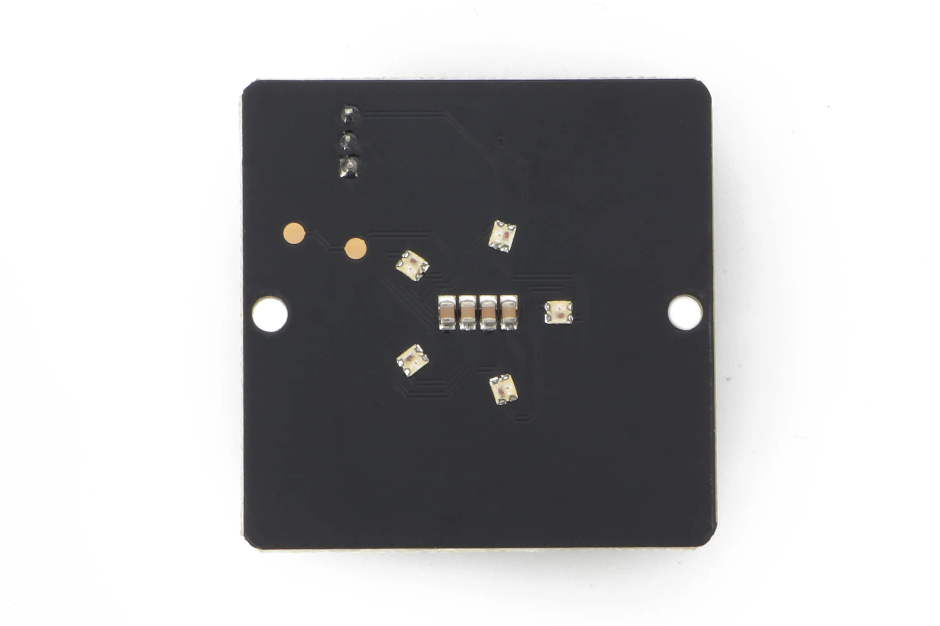
- Press the button briefly to step to the next level. The ring shows a white bar — the number of lit segments is the level, from 1 of 5 (6 A) to 5 of 5 (32 A): = 16 A.
- The level can only be changed while no vehicle is connected, so the current never changes mid-charge.
10 · Status light reference
One colour language throughout: green = ready or charging, amber = waiting or caution, blue = paused, red = fault.
| Light | State | Meaning |
|---|---|---|
| Spinning colours | Starting up | Running the self-test — not ready yet |
| Breathing green | Ready | Idle, ready to charge |
| Solid amber | Connected | Vehicle plugged in, not drawing power yet |
| Moving green | Charging | Delivering power |
| Moving yellow | Charging, reduced | Current reduced to 16 A to protect the board |
| White bar | Level preview | Selected current level after a button press |
| Flashing blue | Paused | Paused by protection — resumes automatically |
| Solid red | Residual current fault | Charging stopped |
| Flashing red | Over-temperature fault | Charging stopped |
| Red / blue | Over-current fault | Charging stopped |
11 · Troubleshooting
The board fails safe: on a fault it opens the relays and shows red. Most faults clear with a power cycle once the cause is removed.
| What you see | Meaning | What to do |
|---|---|---|
| Solid red | Residual current fault | Unplug the vehicle. Switch the circuit off and on. If it returns, stop using the charger and contact support. |
| Solid red right after power-up | Self-test failed | Do not use. Power-cycle once; if it persists, contact support. |
| Flashing red | Over-temperature | Unplug and let it cool. Check the enclosure isn’t covered or in direct sun. Power-cycle. |
| Red / blue | Over-current | Unplug and power-cycle. If it repeats, have the installation and vehicle checked. |
| Flashing blue | Paused by protection | Wait — charging resumes automatically. Repeated pauses point to a supply or vehicle issue. |
| Moving yellow | Reduced current | Normal. Full current returns when the board cools or the car unplugs. |
| No lights | No power | Check the circuit breaker and the supply. |
12 · Maintenance
- Keep the enclosure and its vents clean and unobstructed.
- Wipe with a dry or slightly damp cloth — no solvents or water jets.
- Inspect the cable and connector for damage before each use.
- Power-cycle periodically to re-run the self-test, and have the installation inspected by an electrician at the interval set by local regulations.
13 · Technical reference
Control pilot states
The board advertises the available current on the control pilot as a 1 kHz PWM signal (duty cycle = current ÷ 0.6) and reads the vehicle’s state from the pilot voltage.
| State | Pilot | Behaviour |
|---|---|---|
| A | +12 V | No vehicle. Relays open, no PWM. |
| B | +9 V | Vehicle connected, not requesting power. PWM on, relays open. |
| C | +6 V | Vehicle requesting power. Relays close. |
| F | −12 V | Fault signalled to the vehicle. Relays open. |
A pause (C → B) opens the relays but keeps the PWM running so the vehicle can resume. Unplugging (→ A) opens the relays and stops the PWM.
Protection behaviour
| Protection | Trigger | Response | Clears |
|---|---|---|---|
| Residual current | Type B sensor trip or sensor error | Relays open, state F, solid red | Power cycle |
| Self-test | Fails at power-up | Charging disabled, solid red | Power cycle |
| Over-current | 33.5–35.5 A for 3 s | 120 s pause, flashing blue | Automatically |
| Over-current | ≥ 35.5 A, or more than 3 pauses in a session | Relays open, state F, red / blue | Power cycle |
| Over-temperature | ≥ 90 °C board temperature | Derate to 16 A, moving yellow | ≤ 83 °C or unplug |
| Over-temperature | ≥ 105 °C | Relays open, state F, flashing red | Power cycle |
| Over-voltage | Sustained above 270 V | MOV clamps, fuse opens | Service |
14 · Glossary
| Term | Meaning |
|---|---|
| EVSE | Electric vehicle supply equipment — the charger |
| Control pilot (CP) | Signal line the charger and vehicle use to negotiate charging (IEC 61851-1) |
| RCD | Residual current device — trips on earth-leakage current |
| Type B | Detects AC, pulsating DC and smooth DC residual currents |
| IC-CPD | In-cable control and protection device — a portable charger (IEC 62752) |
| Derate | Temporary reduction of charging current to protect the board |
| PE | Protective earth |
Questions, samples or volume orders? Contact us.